
Learn the physics behind the lab.
Four short readings on the ideas the Engineering Lab uses. Each gives the main ideas and equations of one subject, links to the lab tools that apply them and lists published references.
General theory only. The lab's models are simplified for learning and are not for design or operational decisions.
Aerodynamics and flight fundamentals
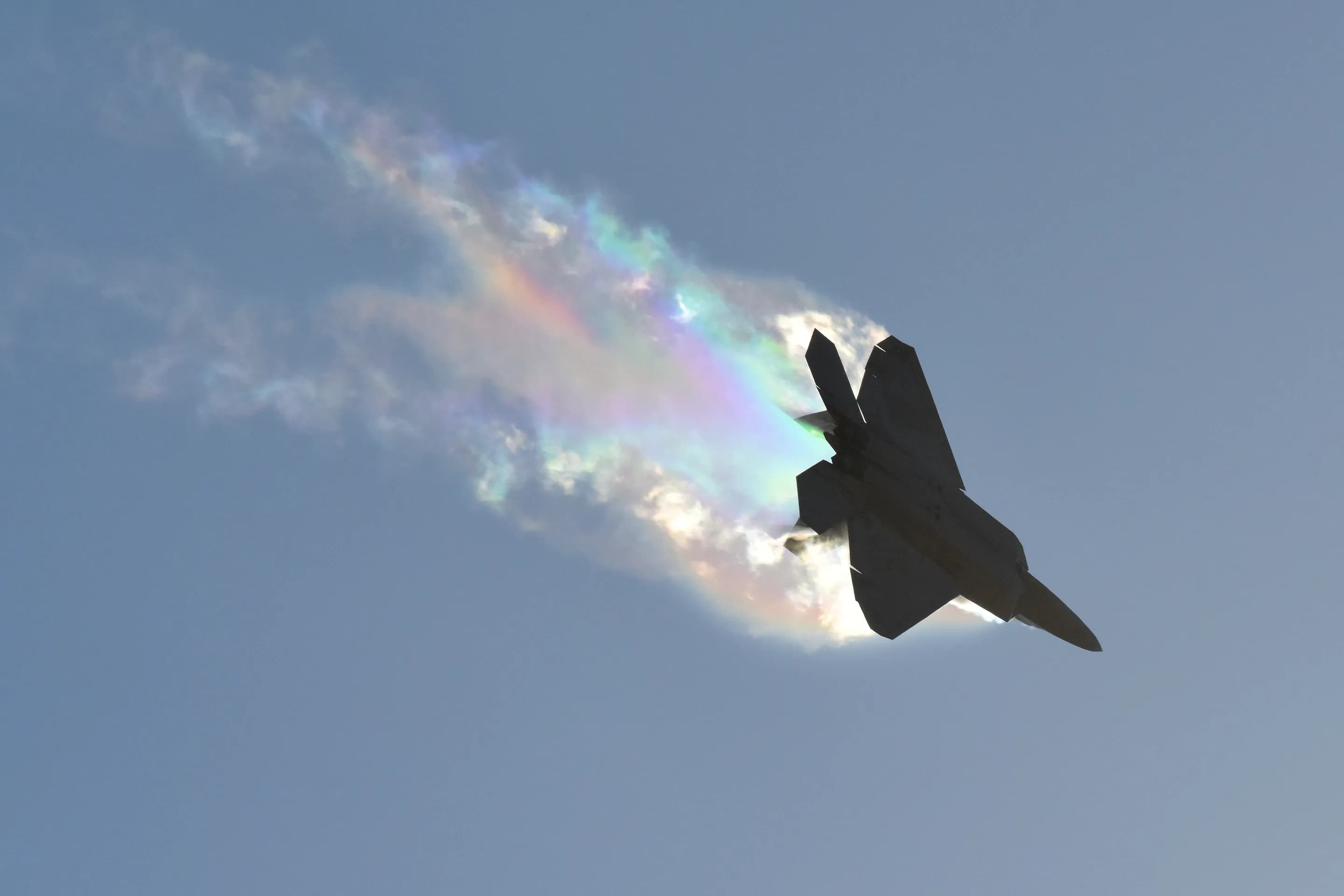
An aircraft in flight is acted on by four forces: lift, weight, thrust and drag. Lift and drag come from the pressure and friction of air moving over the vehicle. Both grow in proportion to air density and to the square of airspeed. Air density falls with altitude, so the same wing at the same speed produces less lift higher up.
Why it matters
These relationships set a winged vehicle's flight envelope: the minimum speed for level flight, the thrust needed to overcome drag, and how both change with altitude. Sizing a wing and choosing a cruise altitude both start from them.

Key ideas
Lift is dynamic pressure, ½ ρ V squared, times the wing's reference area and its lift coefficient.
L equals one half times rho times V squared times S times C L
(1.1)Lift equation, where - L
- Lift, N
- ρ
- Air density, kg/m³
- V
- True airspeed, m/s
- S
- Wing reference area, m²
- CL
- Lift coefficient
Drag has the same form. Its coefficient CD covers skin friction, pressure drag and the drag that comes with producing lift.
D equals one half times rho times V squared times S times C D
(1.2)Drag equation, where - D
- Drag, N
- ρ
- Air density, kg/m³
- V
- True airspeed, m/s
- S
- Wing reference area, m²
- CD
- Drag coefficient
In steady, level, unaccelerated flight, lift equals weight and thrust equals drag.
The lift coefficient rises with angle of attack until the wing stalls. Past the stall angle, lift falls.
A standard atmosphere model gives reference values of temperature, pressure and density at each altitude. Conditions on a given day differ from it.
Further reading
- Lift EquationNASA Glenn Research Center, Beginner's Guide to Aeronautics
- Drag EquationNASA Glenn Research Center, Beginner's Guide to Aeronautics
- U.S. Standard Atmosphere, 1976NOAA, NASA and U.S. Air Force, NASA-TM-X-74335, 1976. NASA Technical Reports Server
- Introduction to FlightJohn D. Anderson Jr., McGraw-Hill
Propulsion and vehicle performance
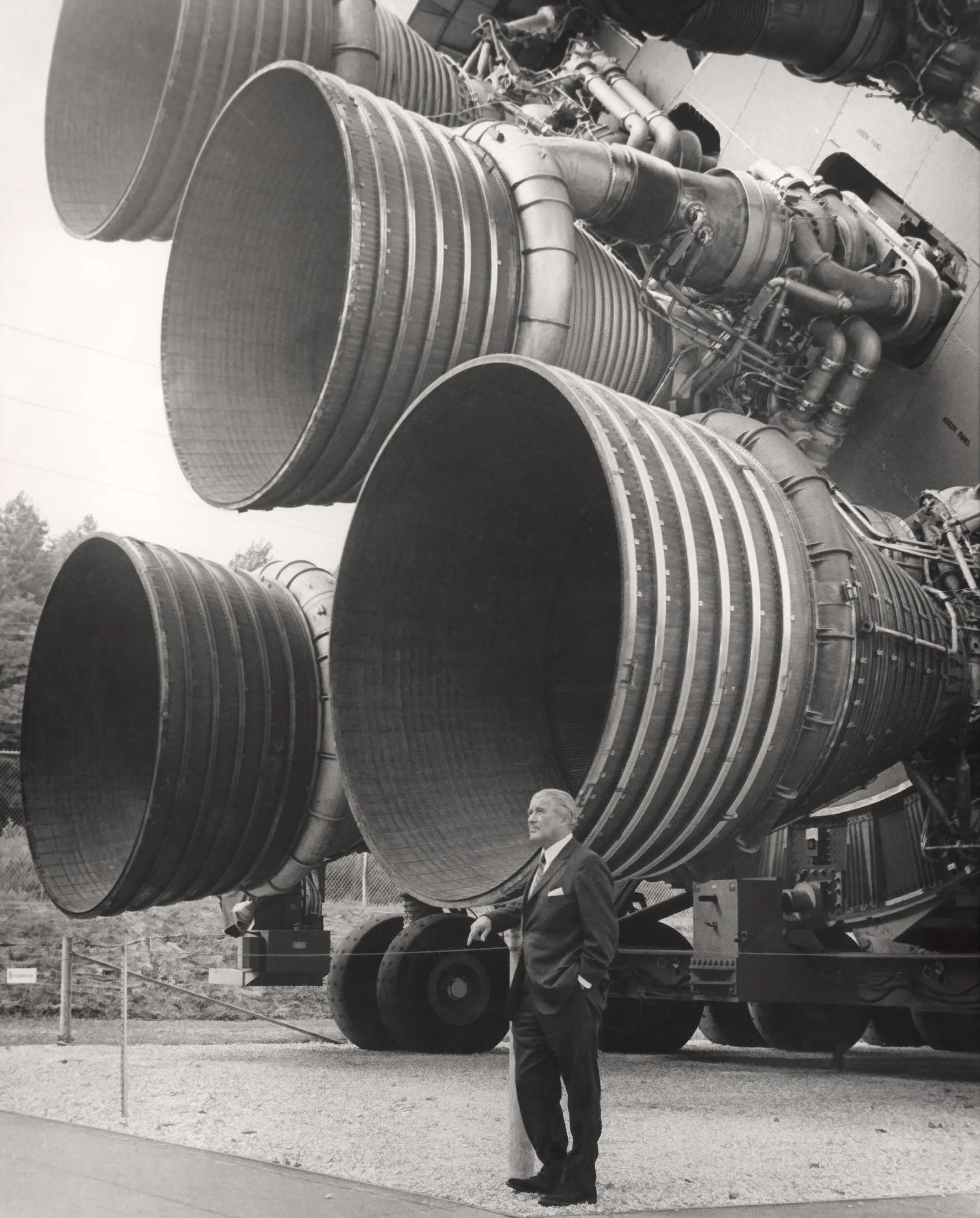
A vehicle accelerates when its thrust exceeds the forces resisting it. For a rocket, the ideal rocket equation links the velocity change a stage can deliver to two quantities: the exhaust velocity of its engines and the ratio of its mass before and after the burn.
Why it matters. Thrust-to-weight ratio affects how quickly an aircraft can climb. Most of a launch vehicle's mass at liftoff is propellant, which is why rocket designs push for high exhaust velocity and drop empty stages on the way up.

Key ideas
A rocket needs a thrust-to-weight ratio above 1 at liftoff to rise vertically. An aircraft can fly with a ratio below 1 because its wings carry its weight.
T over W is greater than 1
(2.1)Thrust-to-weight ratio for vertical liftoff, where - T
- Thrust, N
- W
- Weight, N
In the ideal case, a stage's velocity change comes from two numbers: its effective exhaust velocity and its mass ratio, the mass at ignition over the mass at burnout.
delta v equals v e times the natural log of m zero over m f
(2.2)Ideal rocket equation, where - Δv
- Velocity change of the stage, m/s
- ve
- Effective exhaust velocity, m/s
- m0
- Mass at ignition, kg
- mf
- Mass at burnout, kg
Specific impulse is quoted in seconds. A higher value gives more velocity change from the same propellant mass.
v e equals I s p times g zero
(2.3)Specific impulse, where - ve
- Effective exhaust velocity, m/s
- Isp
- Specific impulse, s
- g0
- Standard gravity, 9.80665 by definition, m/s²
Because the mass ratio sits inside a logarithm, each additional unit of velocity costs more propellant than the last. Staging discards empty tanks and engines so each later stage starts with a better mass ratio.
The ideal equation ignores gravity and drag losses. A real ascent to orbit needs more velocity change than the final orbital speed.
Further reading
- Thrust to Weight RatioNASA Glenn Research Center, Beginner's Guide to Aeronautics
- Ideal Rocket EquationNASA Glenn Research Center, Beginner's Guide to Aeronautics
- Rocket Propulsion ElementsGeorge P. Sutton and Oscar Biblarz, Wiley
High-speed and compressible flow
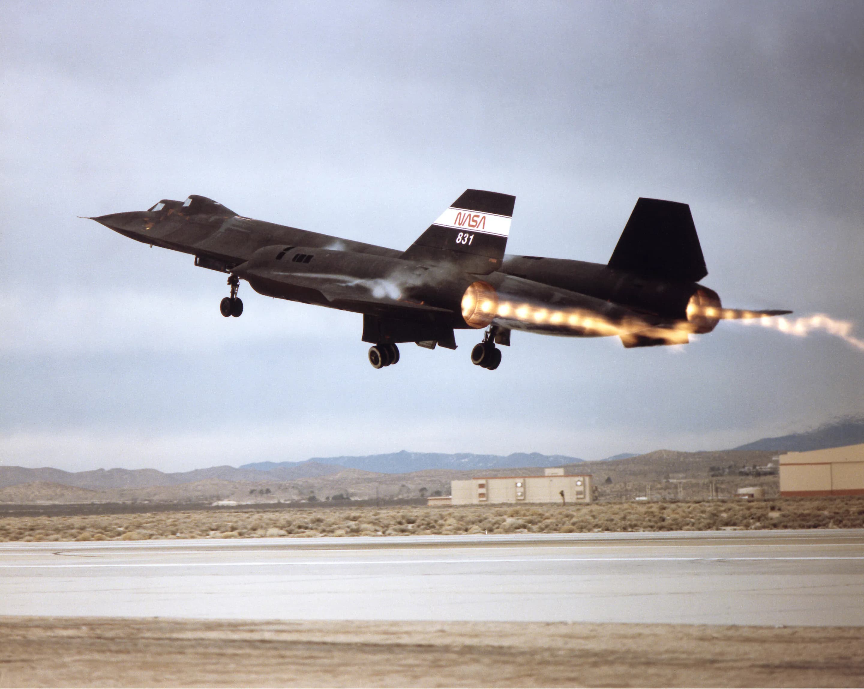
At low speed, air density barely changes as air flows around a body. Near and above the speed of sound, air compresses noticeably. Where the flow is supersonic it adjusts to an obstacle through shock waves: thin regions across which pressure, temperature and density change abruptly.
Why it matters. Supersonic aircraft and their engine inlets are shaped to control where shocks form and how strong they are. A strong shock loses total pressure, which lowers the pressure at the engine face and adds drag.

Key ideas
The speed of sound depends on the air's temperature, so the same flight speed gives a different Mach number in colder or warmer air.
M equals V over a. a equals the square root of gamma times R times T
(3.1)Mach number, where - M
- Mach number
- V
- Flow speed, m/s
- a
- Local speed of sound, m/s
- γ
- Ratio of specific heats, about 1.4 for air
- R
- Specific gas constant, in J/(kg K)
- T
- Static temperature, K
Changes in air density are usually ignored below about Mach 0.3. Above that, the compressible flow relations are needed.
Stagnation (total) temperature and pressure are the values the flow would reach if it were slowed to rest without losses. They are the reference values for the isentropic flow relations.
A normal shock turns supersonic flow subsonic. Static pressure, temperature and density rise across it, and total pressure falls.
An oblique shock turns the flow through an angle and is weaker than a normal shock at the same Mach number. Supersonic inlets use one or more oblique shocks before a final normal shock, which loses less total pressure than a single normal shock.
Further reading
- Equations, Tables, and Charts for Compressible FlowAmes Research Staff, NACA Report 1135, 1953. NASA Technical Reports Server
- Isentropic Flow EquationsNASA Glenn Research Center, Beginner's Guide to Aeronautics
- Normal Shock Wave EquationsNASA Glenn Research Center, Beginner's Guide to Aeronautics
- Oblique Shock WavesNASA Glenn Research Center, Beginner's Guide to Aeronautics
Orbital mechanics and mission design
A spacecraft changes orbit by firing its engines to change its velocity. The total velocity change a mission needs, its delta-v budget, is the main measure of how demanding the mission is, because the rocket equation converts it directly into propellant mass.
Why it matters. Mission designers order and combine maneuvers to keep the delta-v budget within what the vehicle can deliver. Raising a satellite to its operating orbit and departing for another planet are both planned this way.
Key ideas
The larger the orbit, the slower a spacecraft in it moves.
v equals the square root of mu over r
(4.1)Circular orbital speed, where - v
- Circular orbital speed, m/s
- μ
- Gravitational parameter of the central body, m³/s²
- r
- Orbit radius, from the center of the central body, m
A Hohmann transfer moves between two circular, coplanar orbits with two burns: one to enter an elliptical transfer orbit, and one to circularize at the far end. For most pairs of orbits it is the two-burn transfer with the lowest delta-v.
The cost of tilting the orbit grows with speed, so plane changes are cheapest where the spacecraft moves slowest, such as at apoapsis.
delta v equals 2 v times the sine of delta i over 2
(4.3)Plane change, where - Δv
- Velocity change of the burn, m/s
- v
- Orbital speed at the burn, m/s
- Δi
- Change in orbit plane angle
Burns can be combined. A plane change made during a transfer burn usually costs less than the two made separately.
Further reading
- Chapter 4: TrajectoriesNASA Science, Basics of Space Flight
- Orbital Mechanics for Engineering StudentsHoward D. Curtis, Butterworth-Heinemann
- Fundamentals of AstrodynamicsRoger R. Bate, Donald D. Mueller and Jerry E. White, Dover